Setup guide part 2.
Installing the DeckHD Screen on Steam Deck.

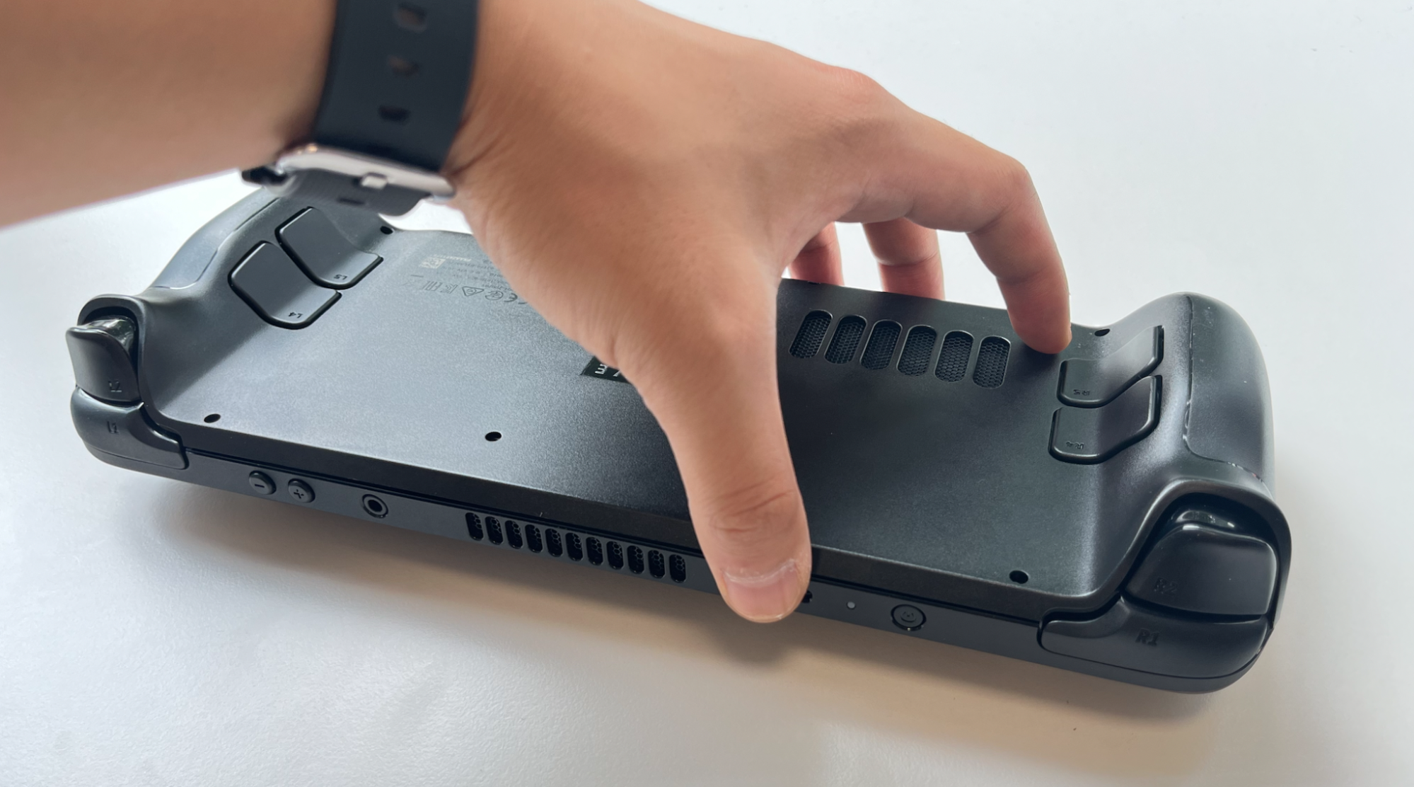
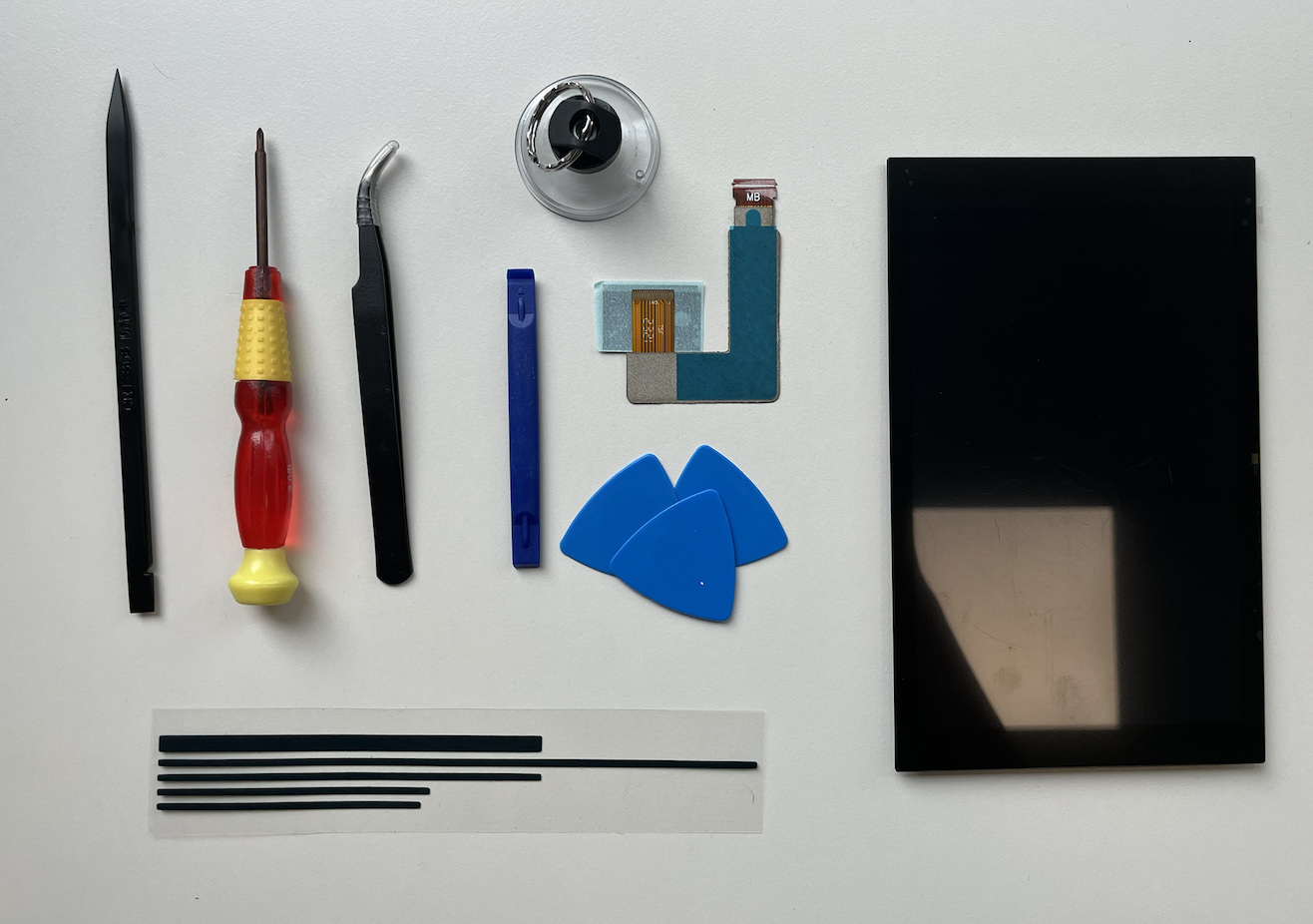
This guide will walk you through the process of effectively replacing the screen on your Steam Deck with the new and upgraded DeckHD screen. Prioritise your safety by following general electrostatic discharge (ESD) safety measures throughout the repair procedure.

Approx. 2 hrs.

Toolkit contents

  • Opening Picks
  • Spudger
  • Opening Tool
  • Suction Handle
  • Tweezers
  • 2.0mm Screwdriver
  • Adhesive Strips

Step 1. Remove the back cover screws

  1. Use a screwdriver to remove the eight screws securing the back cover:
    - Four 9.5 mm screws (purple)
    - Four 5.8 mm screws (yellow)
  2. Keep track of each screw throughout the repair and ensure it goes back exactly where it came from to avoid damaging your Steam Deck.

Step 2. Unclip the back cover

  1. Insert an opening pick into the thin gap between the back cover and the front shell, along the edge of the right grip.
  2. If you're having trouble inserting the pick at the grip seam, try starting at either the top or bottom long edges first, then slide the pick towards the grip.
  3. Pry up on the back cover to release it from the locking clips.

Step 3. Remove the back cover

Once the clips are disconnected from one edge, the rest will detach easily.

  1. Grip the back cover at the opening you created and pull it up and away from the device to unclip the long edges.
  2. Remove the back cover.

Step 4. Uncover the hidden shield screw

  1. Use a pair of tweezers to remove the piece of foil tape covering the hidden screw on the board shield.
  2. If possible, avoid ripping or tearing the tape to reuse it. Otherwise, you can fashion a replacement by cutting a piece of aluminium foil tape to fit.

Step 5. Remove the shield screws

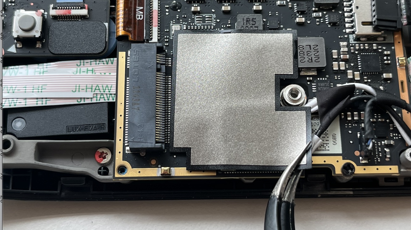
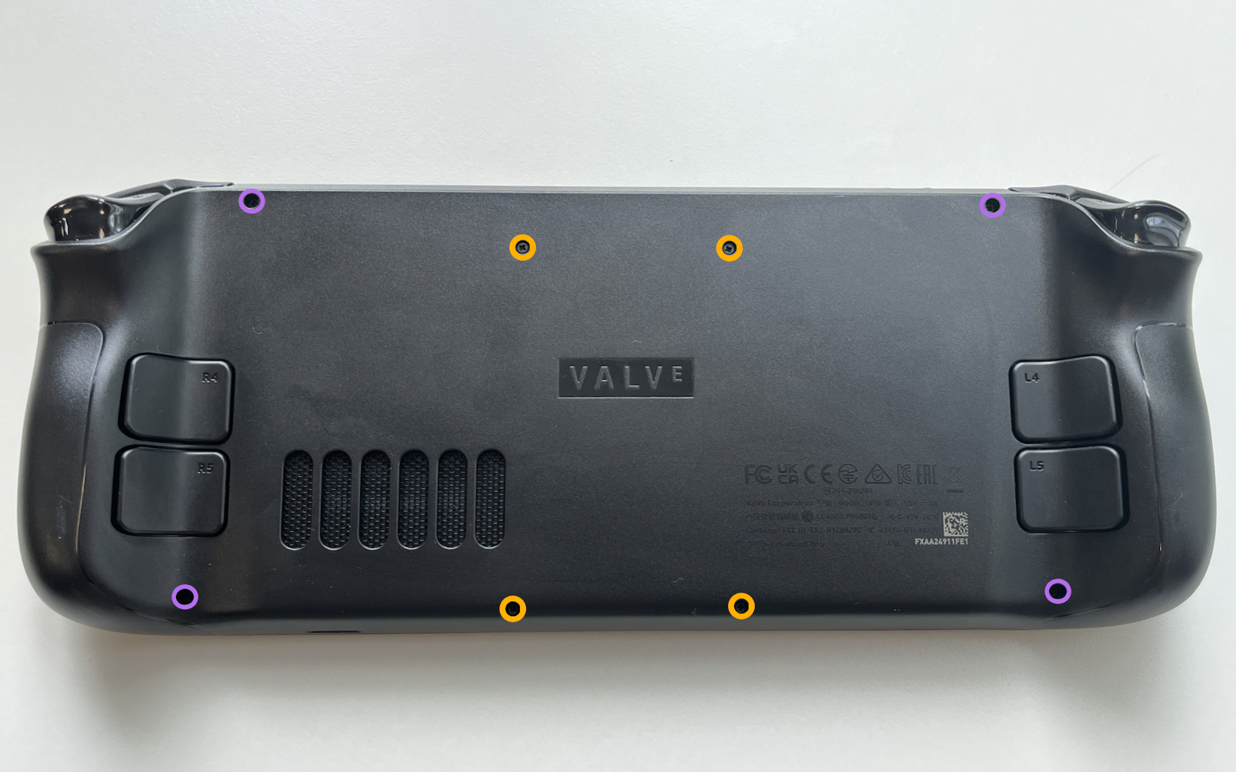
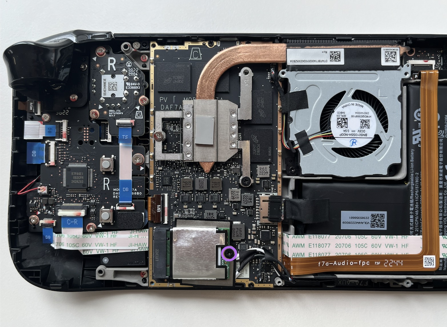
Use the driver to remove the three screws securing the board shield:

  • One 3.4 mm screw (yellow)
  • Two 3.7 mm screws (purple)


Step 6. Remove the shield

  1. Remove the board shield.
  2. During reassembly, ensure that the fan cable lays on the side of the board shield and isn't pinched underneath.

Step 7. Disconnect the battery

  1. Grip the battery cable by its pull tab and pull it directly away from the motherboard to disconnect it.
  2. Alternatively, use the flat end of a spudger or a clean fingernail to push the connector out of its socket gently, then disconnect it entirely by hand.

Step 8. SSD screw removal

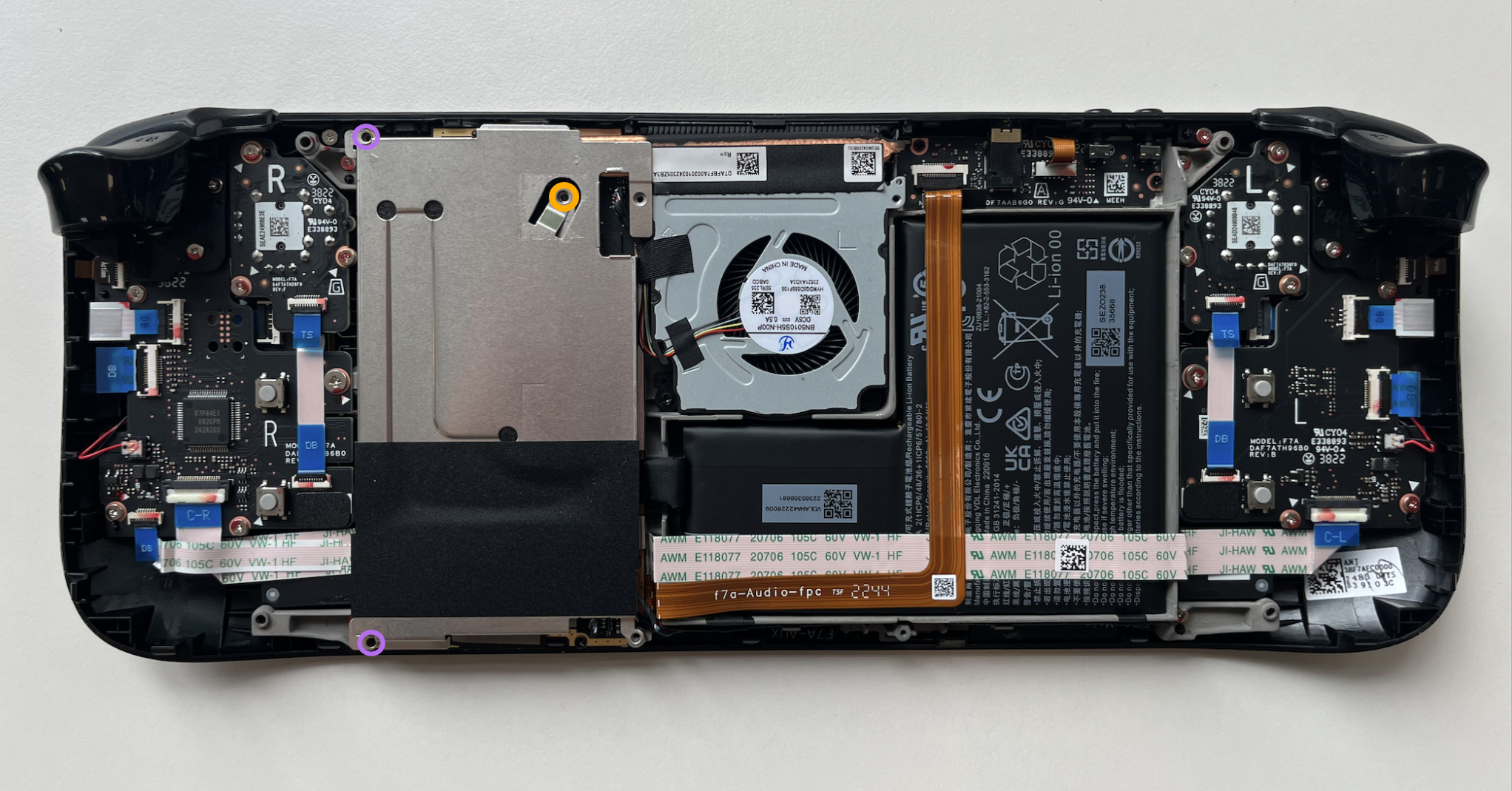
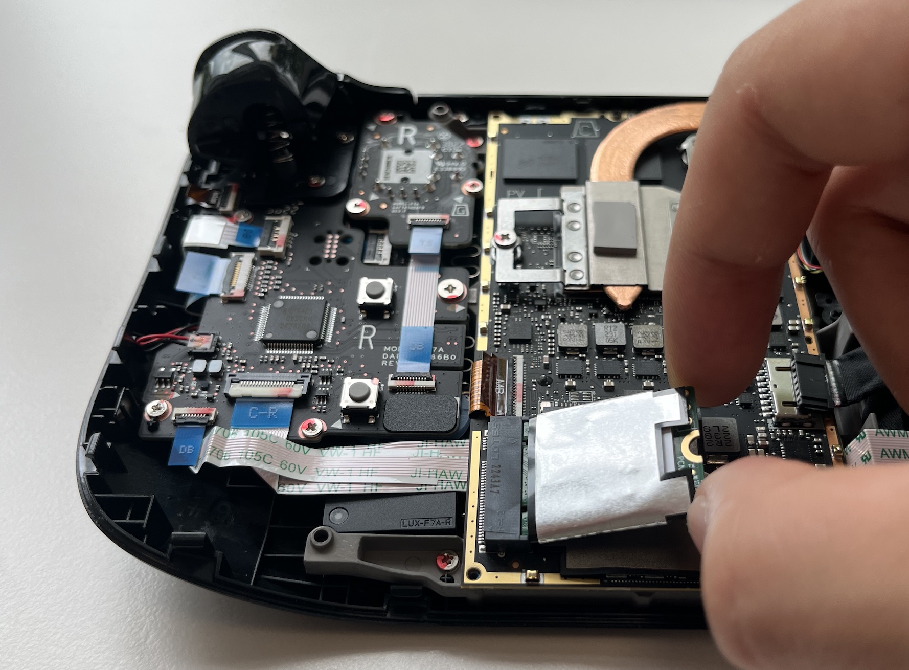
Use the screwdriver to remove the 3.4 mm screw that secures the SSD in place.

Step 9. SSD removal

Once the SSD screw has been removed, gently lift the SSD at a shallow angle. Hold the end of the SSD and pull it away from the M.2 board connector to detach it. When reassembling, insert the SSD into its board connector at a shallow angle and secure it back into a horizontal position using the SSD screw.

Step 10. Heatsink sticker removal

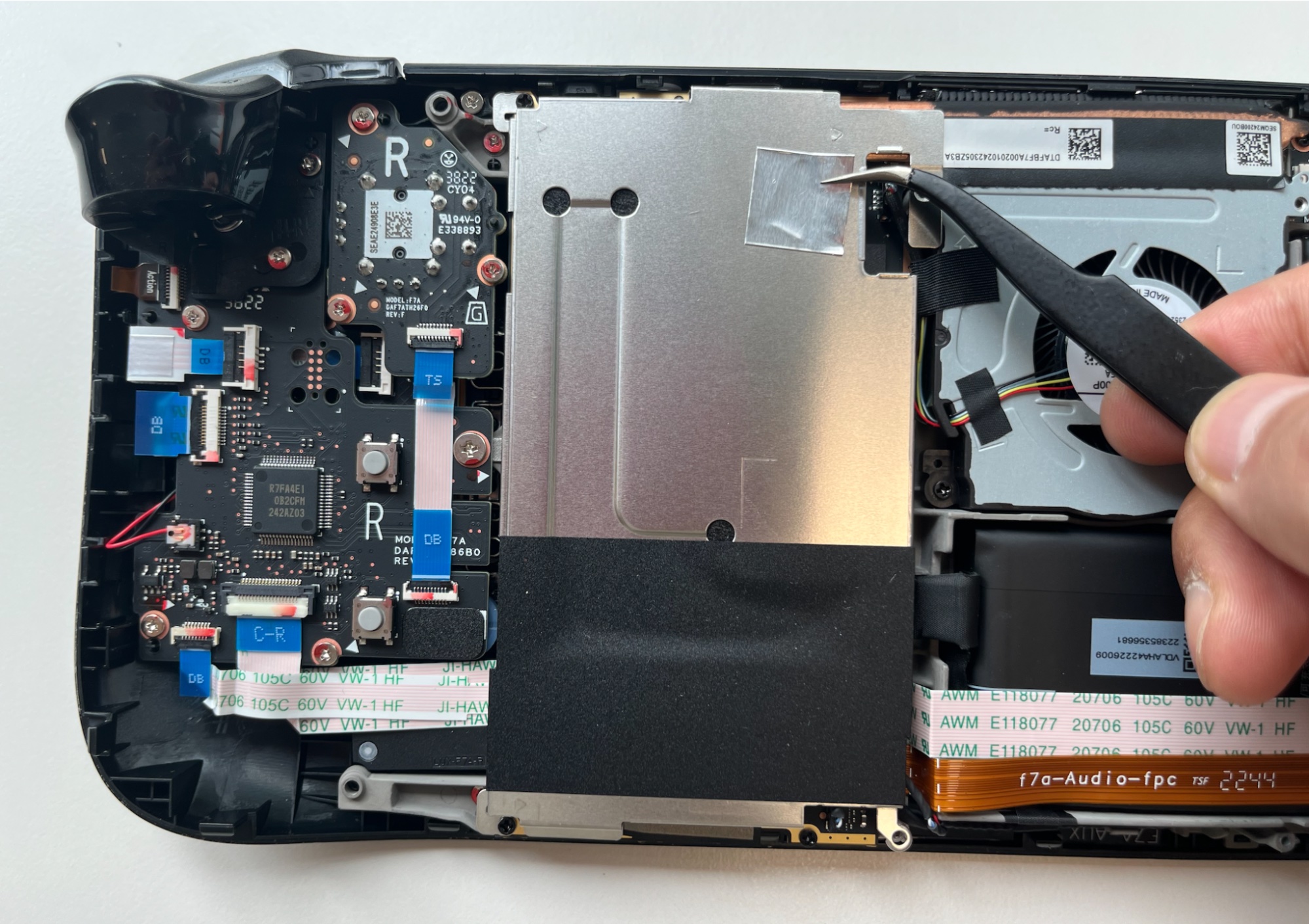
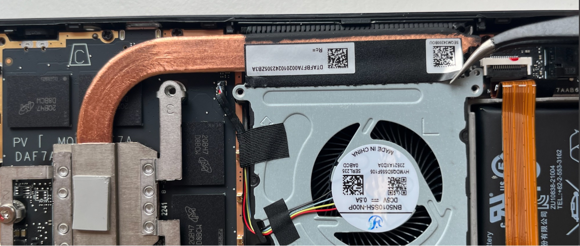
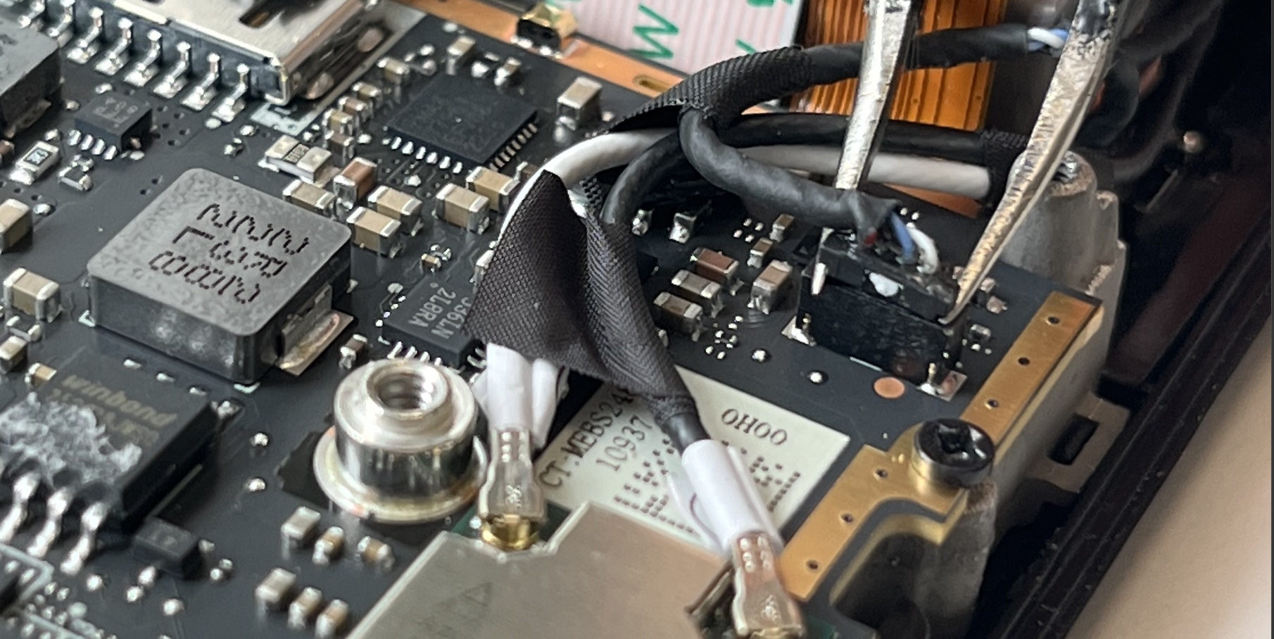
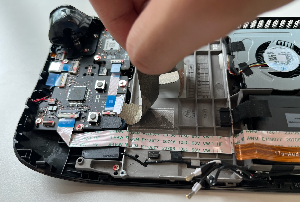
Using a pair of tweezers, carefully remove the sticker from the top edge of the fan. If possible, avoid ripping or tearing the sticker to reuse it. If needed, apply a little heat to soften the adhesive. If the sticker seems prone to tearing, use tweezers to lift one edge until you can grip it with your fingers, and then remove the rest by hand.

Step 11. Heatsink screw removal

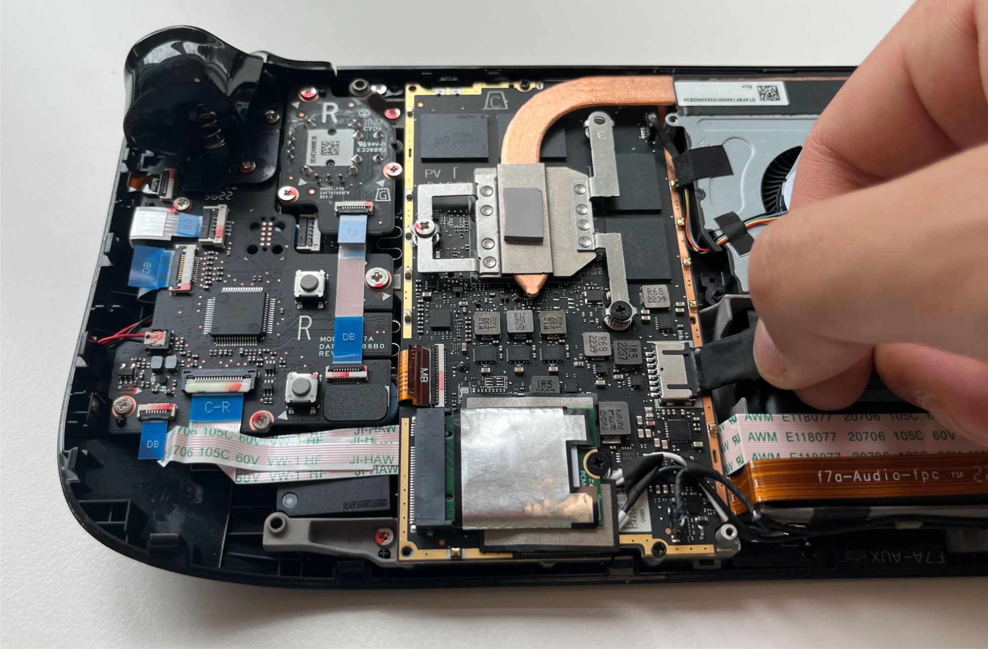
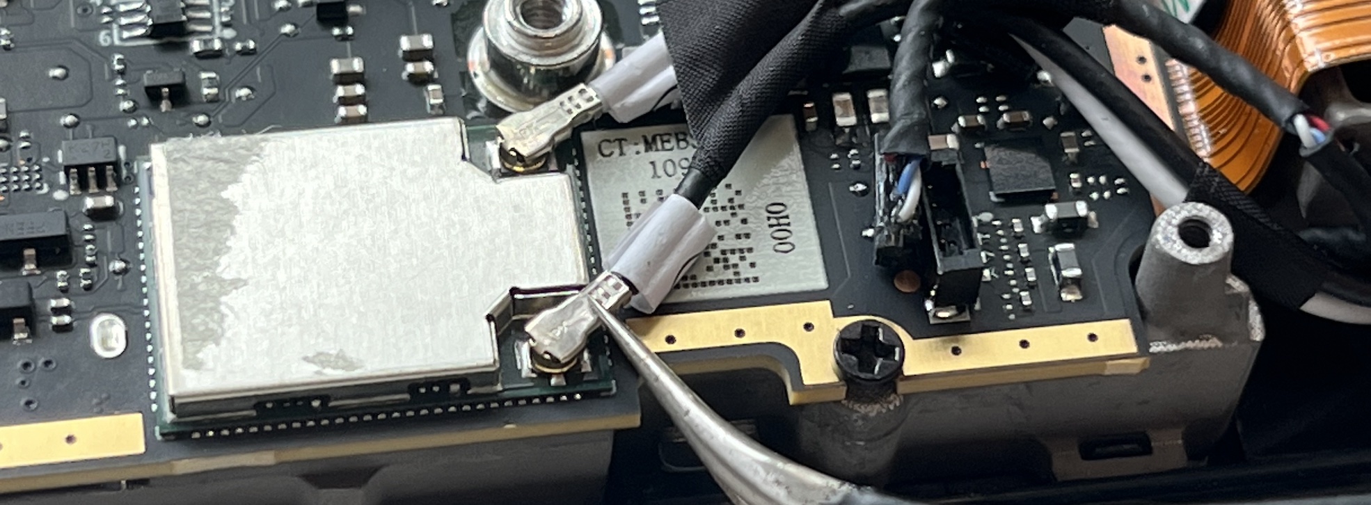
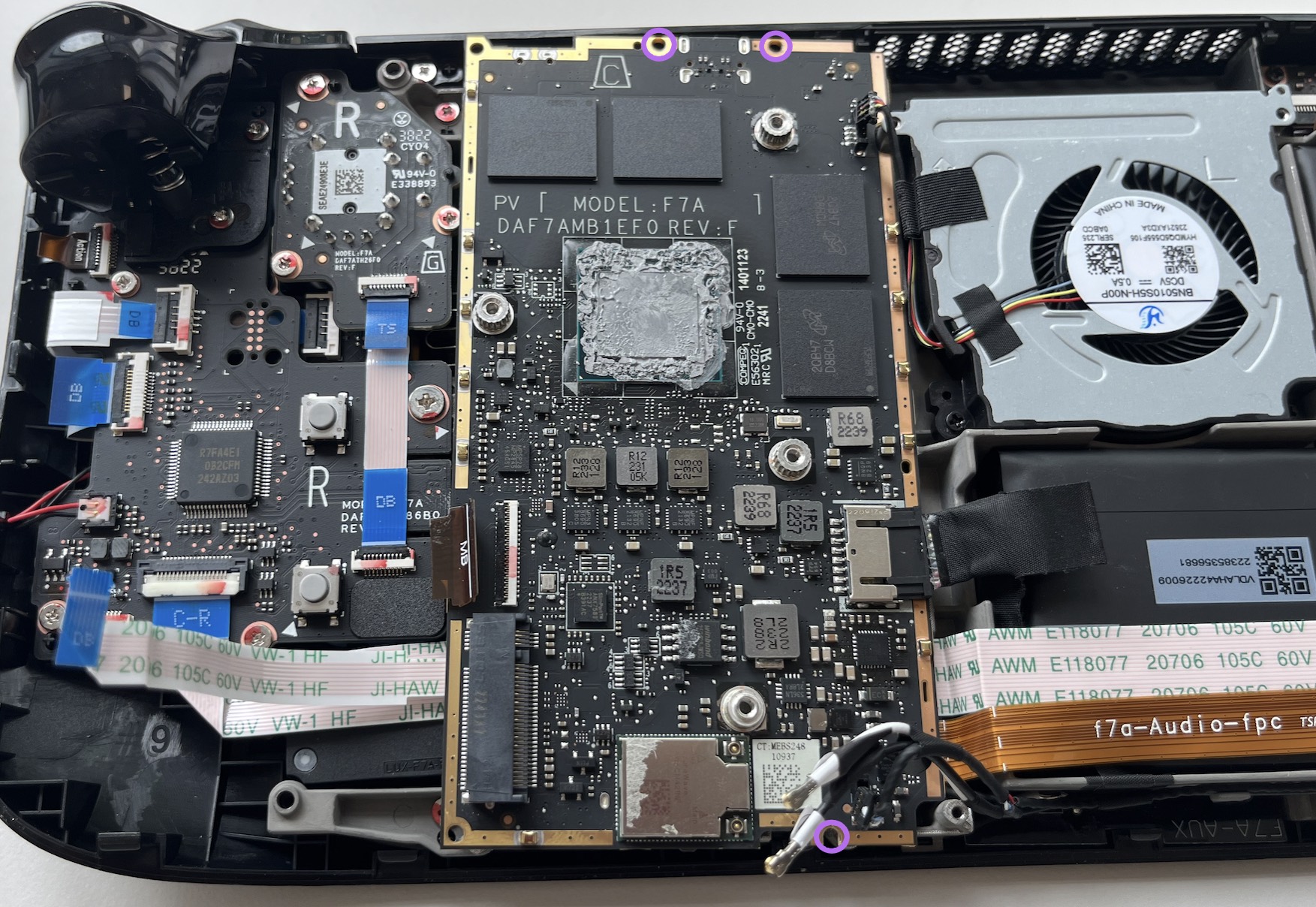
Using the screwdriver, loosen and remove the two screws that secure the heatsink to the motherboard. These include one captive 3.5 mm (yellow) screw and one 3.4 mm (purple) screw. Note that the third heatsink screw was removed during earlier disassembly, as it also serves as the hidden board shield screw.

Step 12. Heatsink removal

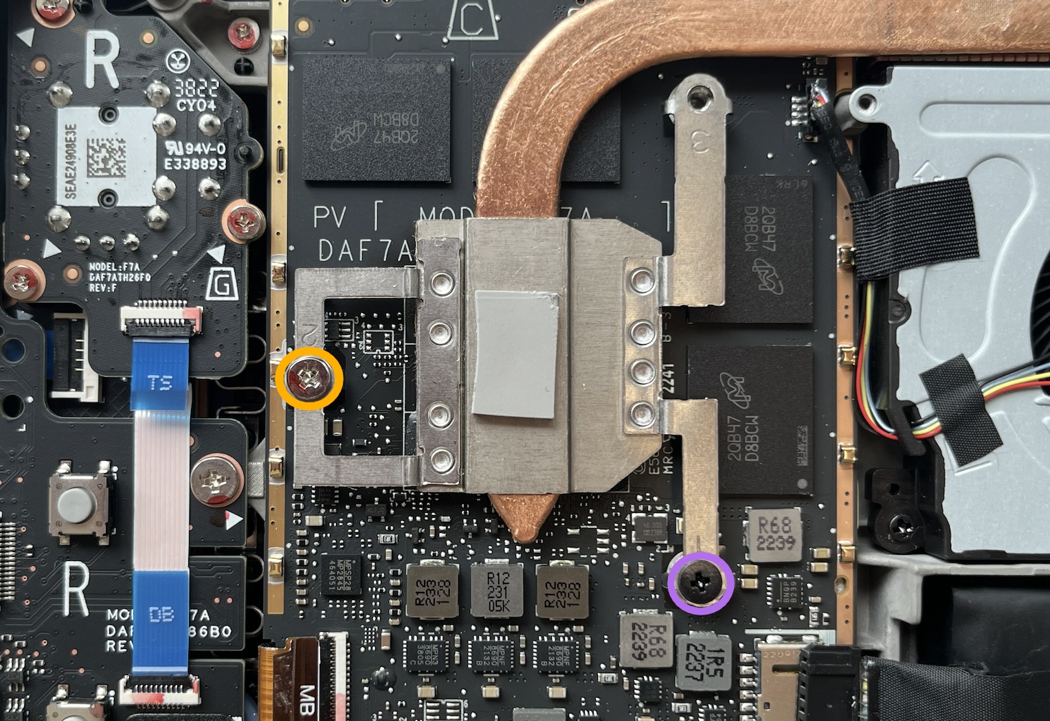
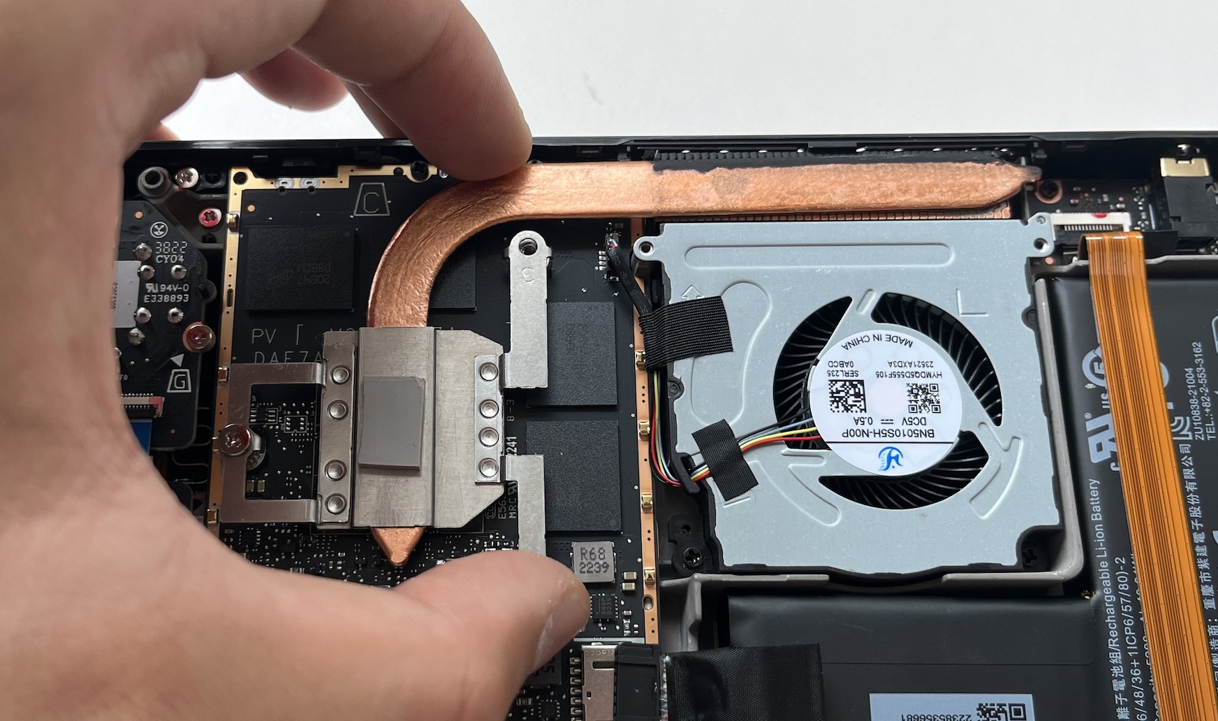
Carefully lift and remove the heatsink from the device. Before reinstalling the heatsink, it is important to clean the heatsink and APU. Additionally, make sure to reapply thermal paste.

Step 13. Fan disconnection

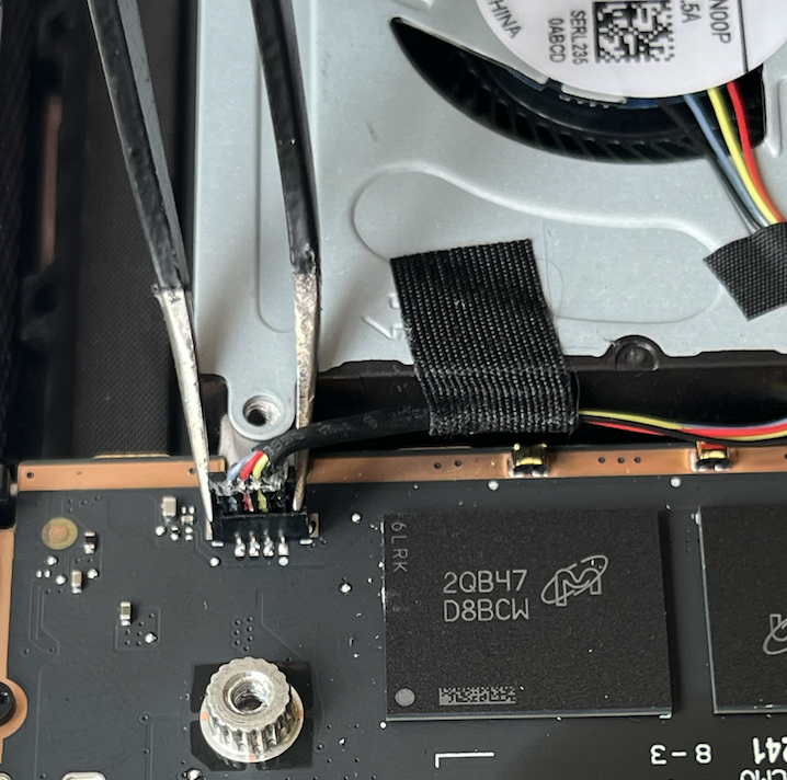
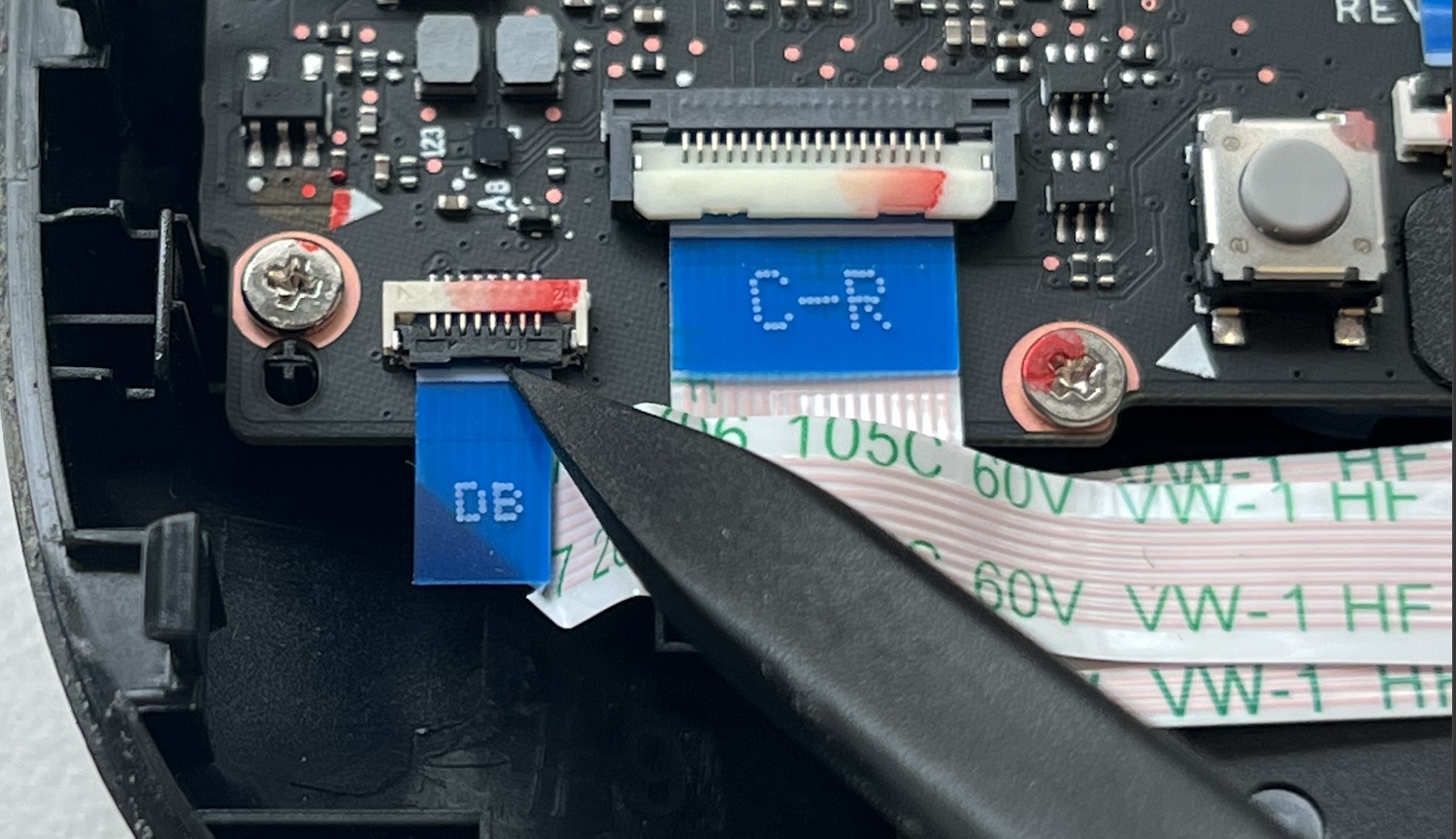
Using a pair of tweezers, grip the edges of the fan connector and pull upwards to disconnect it from the motherboard. Be sure to pull the fan cable by its connector rather than the wires themselves.

Step 14. Removing the Wi-Fi shield tape

  1. To begin, use a pair of tweezers to gently lift and remove the Wi-Fi shield tape.
  2. Be cautious not to tear or damage the sticker, as it can be reused.
  3. If needed, apply a small amount of heat to soften the adhesive.

Step 15. Disconnecting the speakers

  1. With the pair of tweezers, grip the edges of the speaker connector and pull up to disconnect it from the motherboard.
  2. Ensure you pull the speaker cable by its connector, avoiding the wires.

Step 16. Disconnecting the Wi-Fi

  1. Use the pair of tweezers to grip the antenna connector near its base.
  2. Pull the connector straight up to disconnect the cable.
  3. Repeat this process for the second antenna cable.
  4. During reassembly, ensure both antenna cables are reconnected to their appropriate connectors. Match the labels on the cables with the markings on the Wi-Fi module.
  5. To reconnect each cable, align the connector directly over its socket and press down firmly until it snaps into place.

Step 17. Disconnecting the display

  1. Take the pointed end of a spudger and lift the small locking flap on the display cable's ZIF connector.
  2. Use the pair of tweezers to slide the cable out of the connector.
  3. Grip the cable by its pull tab, not the cable itself.

Step 18. Disconnecting the button board

  1. Using the pointed end of a spudger, gently lift up the small locking flap on the ZIF connector of the button board cable.
  2. With a pair of tweezers, carefully slide the cable out of its connector.
  3. It's important to grip the cable by the blue pull tab rather than the cable itself to avoid damage.

Step 19. Removing the motherboard screws

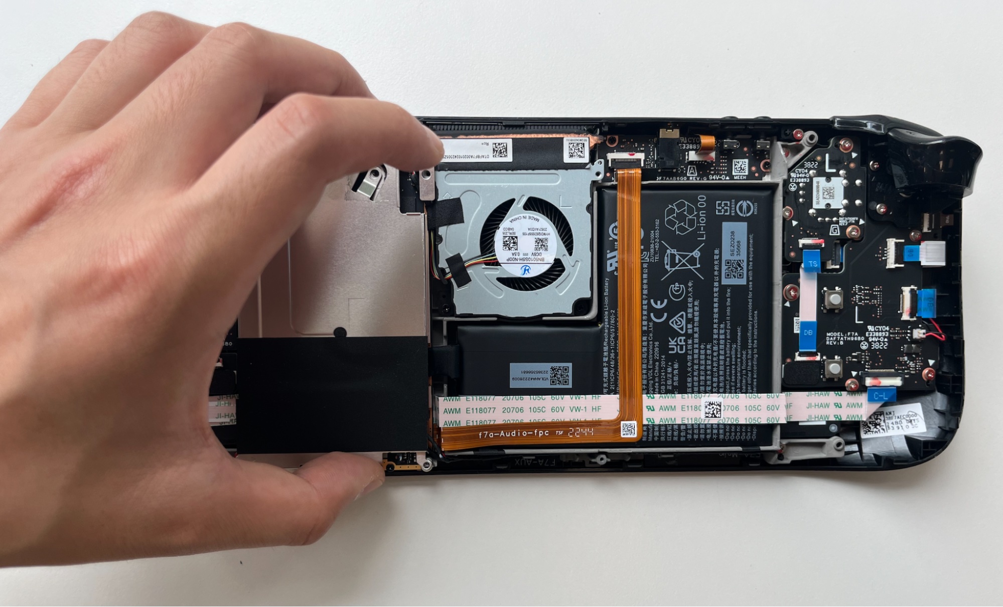
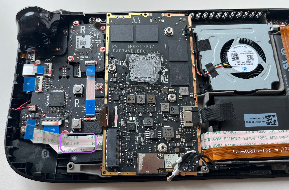
Use a Phillips driver to remove the three 3.7 mm screws that secure the motherboard.

Step 20. Removing the motherboard

  1. Note that there is a thin layer of double sided tape stuck in between the two left hand side button board cables. Gently peel and separate the upper cable to allow the motherboard to be moved.
  2. Carefully lift the motherboard from the left side and tilt to the right, revealing the audio cable connector attached to the underside of the motherboard.

Step 21. Disconnect the audio cable

  1. Use the pointy end of the spudger to flip the locking flap to release the ZIF connector
  2. Gently wiggle the cable and pull out the connector
  3. Place aside the detached motherboard for the assembly process afterwards

Step 22. Uncovering the Display Connector

  1. Use a pair of tweezers to gently peel back the sticker covering the display connector.
  2. If possible, avoid ripping or tearing the sticker so it can be reused. You may use a little heat to soften the adhesive if necessary.

Step 23. Disconnecting the display

  1. With the pointed end of a spudger, lift up the small locking flap on the ZIF connector of the display cable.
  2. Using a pair of tweezers, carefully slide the cable out of its connector.

Step 24. Peel off the display cable

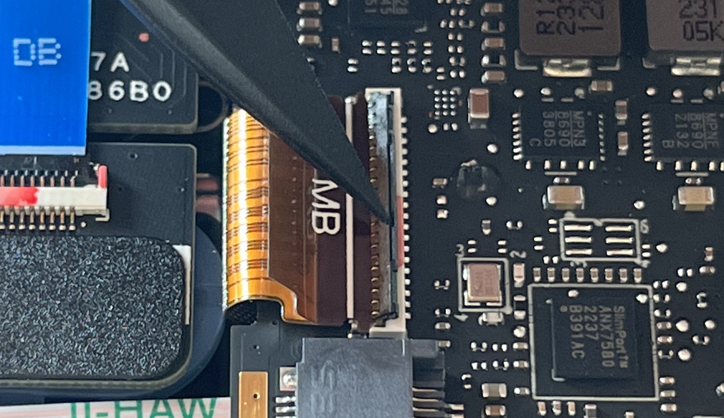
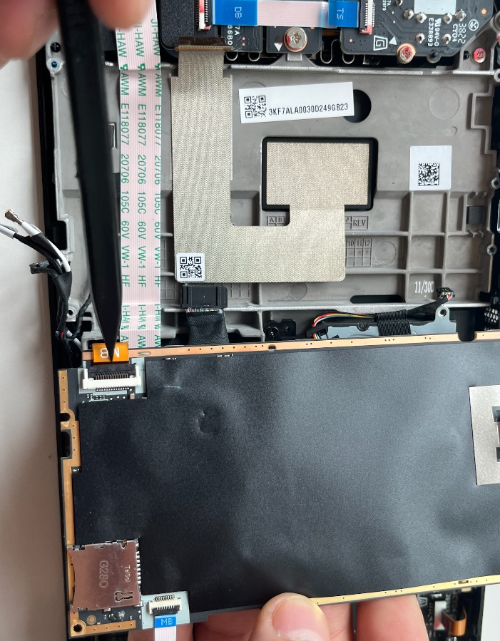
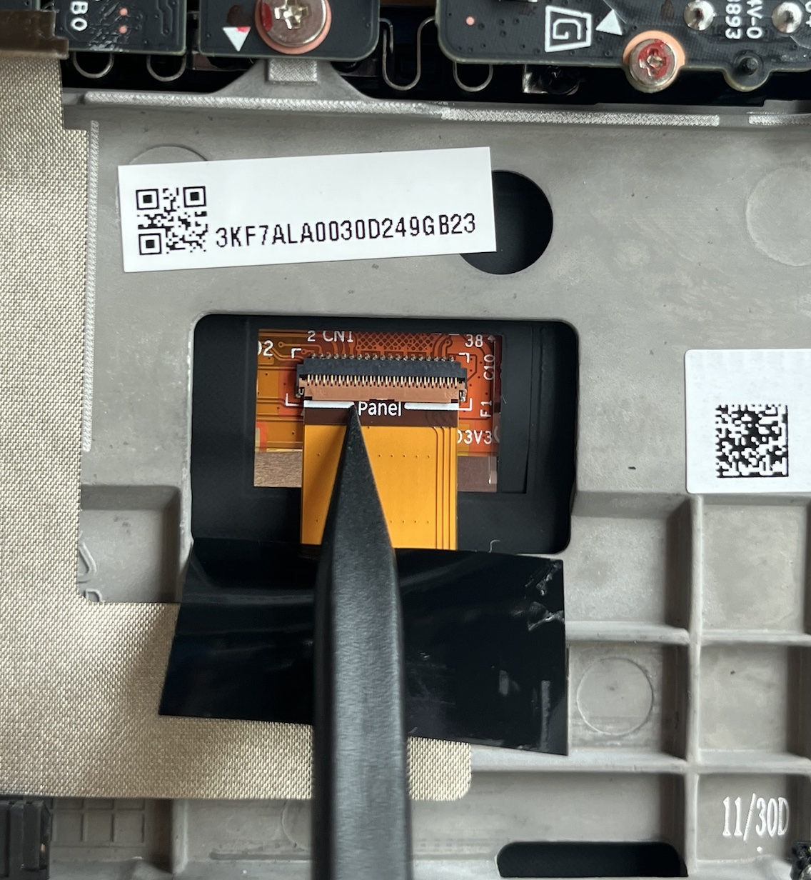
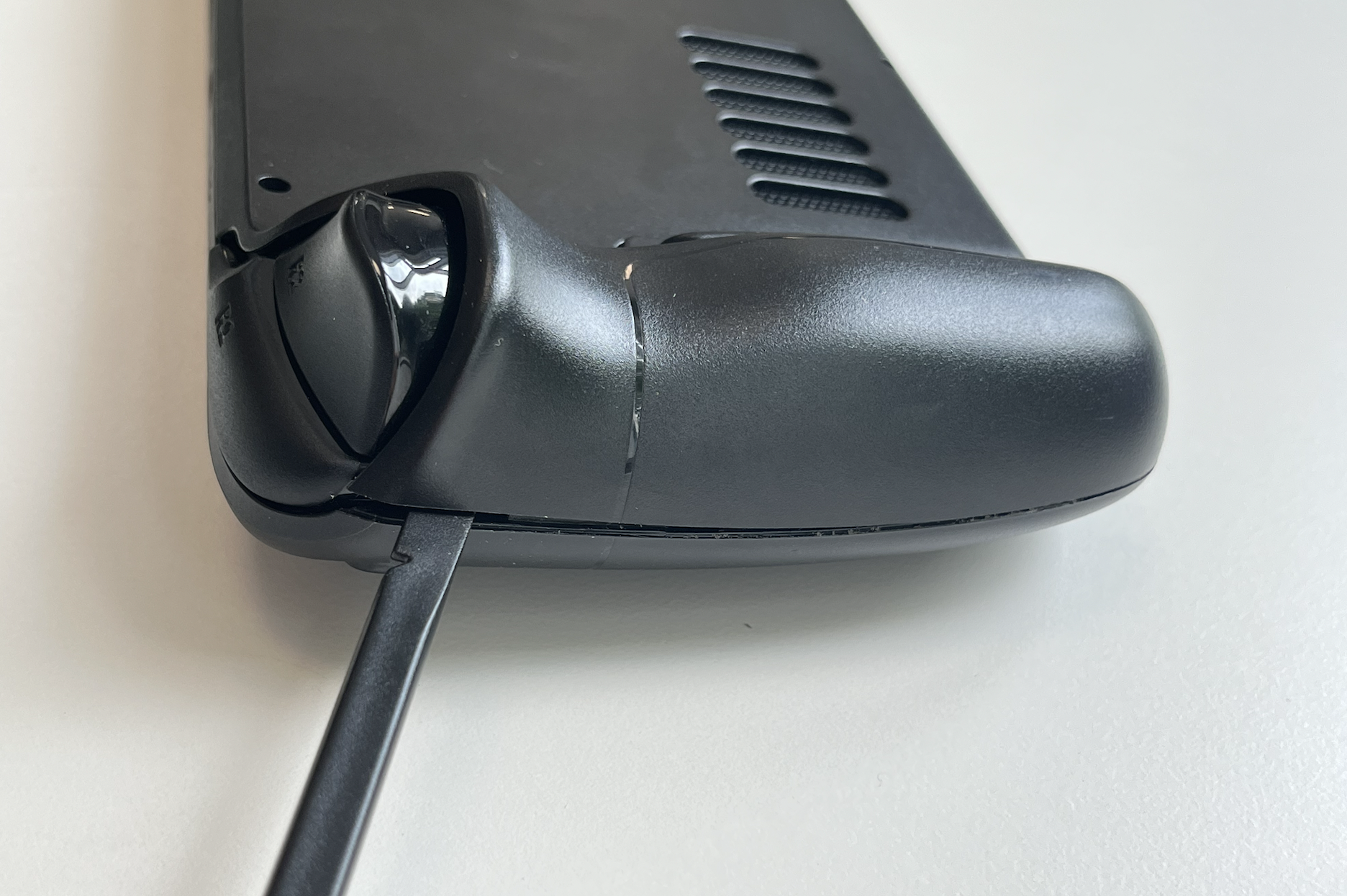
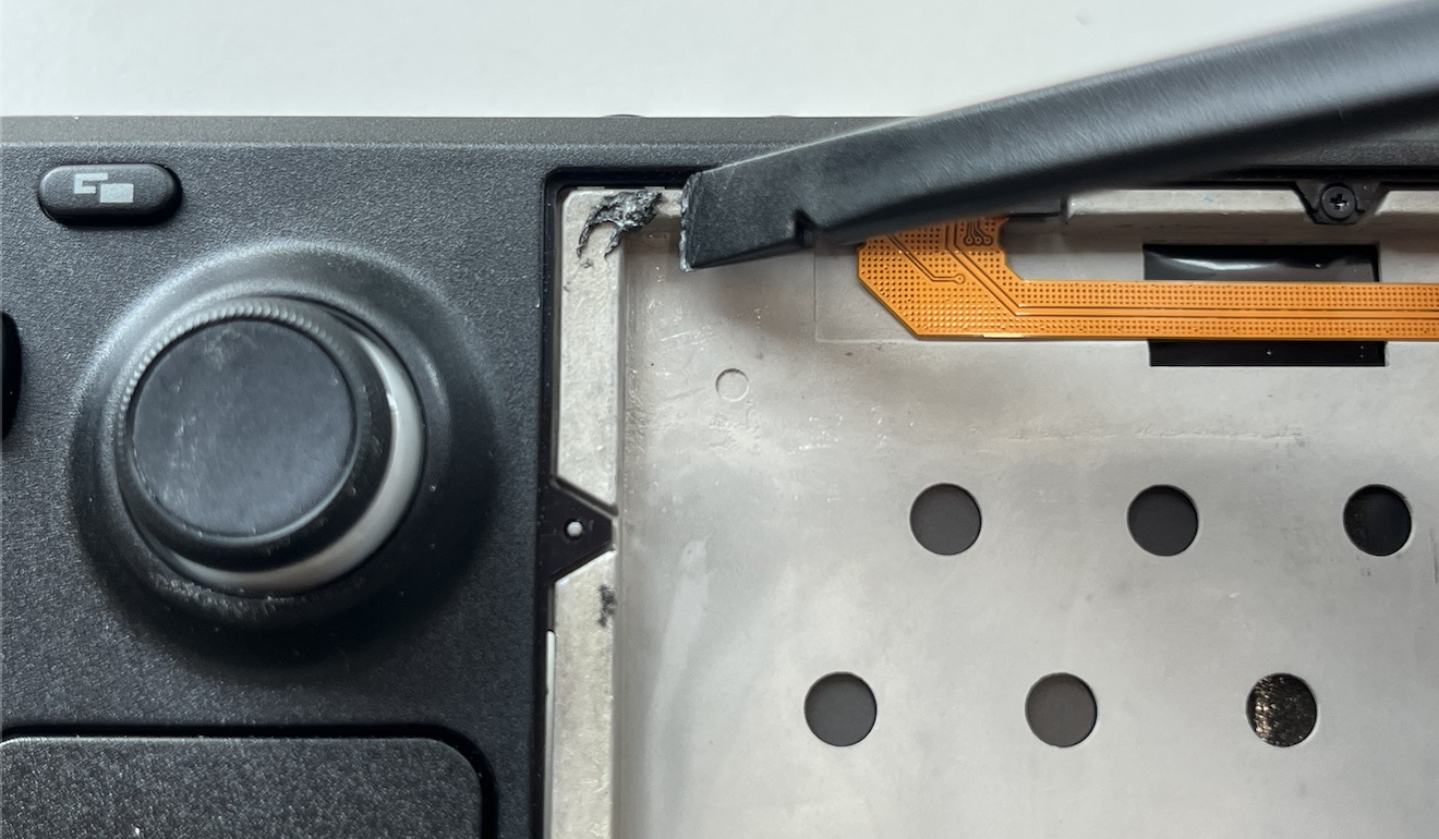
Gently peel off the display cable from the Steam Deck shell. Try to follow the shape of the cable while peeling, this will minimise the chance of any damage to the cable.

When assembling the device back, make sure the connector fits between the white guidelines, in order to align the connector with the port on the motherboard.

Step 25. Heating the display adhesive

Apply heat to each edge of the display for one minute individually. A hair dryer or heat gun may be used. It is essential to avoid overheating the Steam Deck. Displays and internal batteries are both susceptible to heat damage.

Step 26. Applying the suction cup

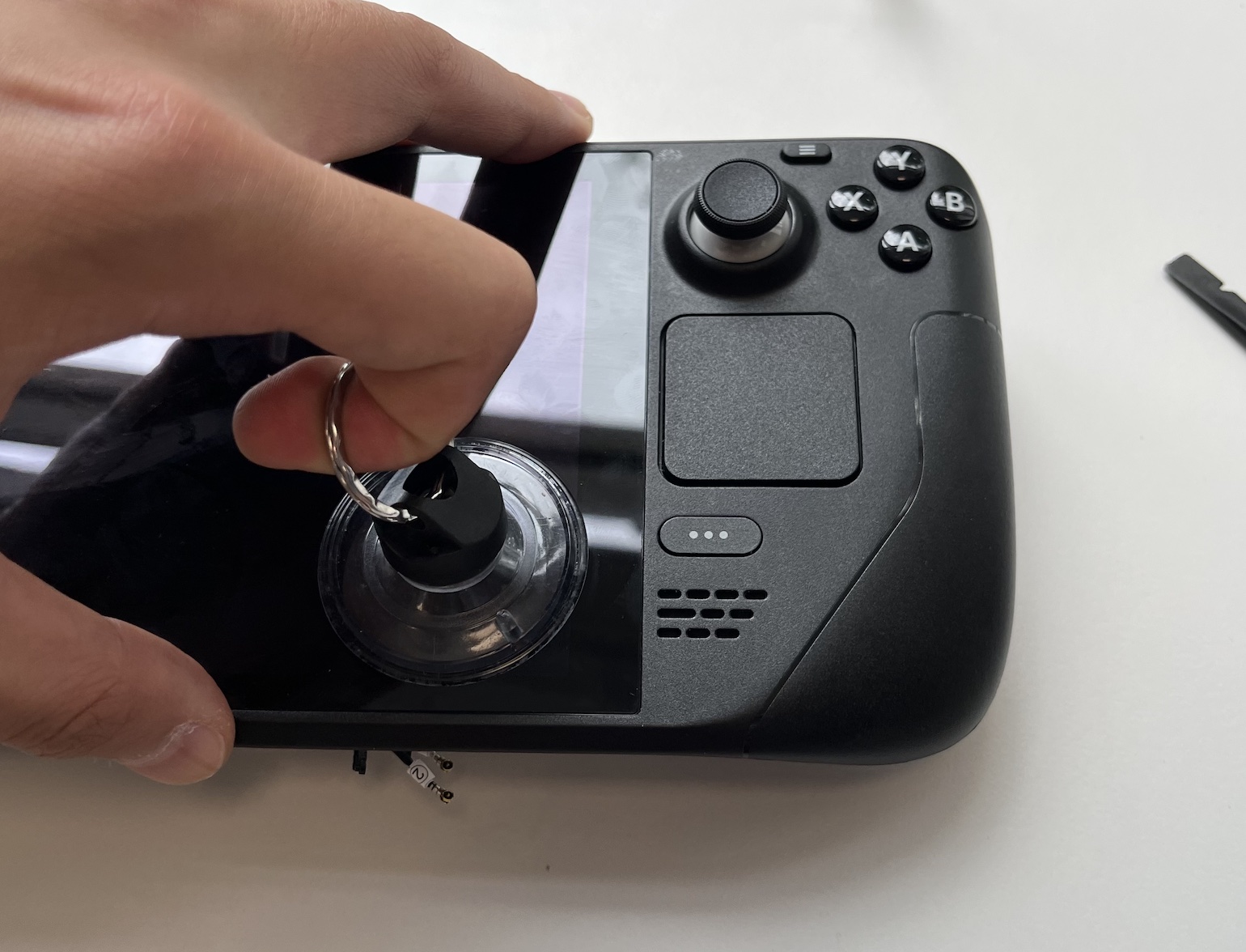
Place and press the suction cup near the edge of the display you’ve just heated.

If your screen is severely cracked, consider covering it with a layer of clear packing tape to enhance the suction cup's adhesion.


Step 27. Insert an opening pick

  1. With a strong and steady force, lift the suction cup upwards to create a gap between the display and the frame.
  2. Gently insert the pointed end of an opening pick into the gap.

    Ensure you do not insert the pick more than 1/8 of an inch (~3 mm) to prevent damage to the display panel, ambient light sensor, or delicate cables underneath.

Step 28. Trim the edges

  1. While pulling on the suction cup, slide the opening pick across the edge of the display to cut through the adhesive.
  2. Remember to reposition your suction cup whenever necessary.
  3. When you feel the edge you’re working on has loosened, place one of the three opening picks in that edge to maintain elevation while  you continue to the next edge.

Step 29. Heat and repeat

  1. Apply heat to the rest of the edges and continue to use the suction cup to separate the screen and the shell while trimming the edges with an opening pick.
  2. Be particularly careful when using the opening pick to trim around the corners. Your screen could crack if too much angle is applied. Therefore, always ensure there’s enough pull force with the suction cup when using the opening pick.

Step 30. Lift up the display

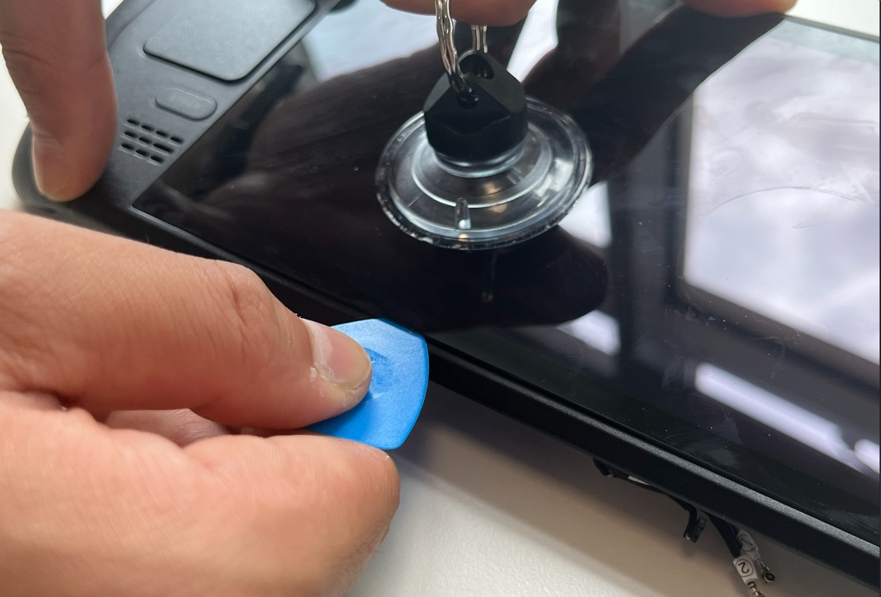
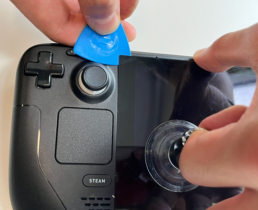
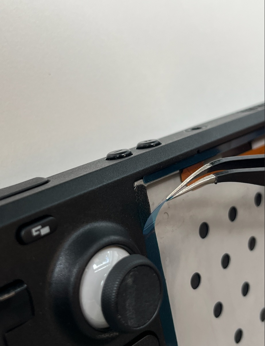
Once all four edges have been trimmed with an opening pick, carefully lift one of the edges up with the help of the suction cup and remove the display.


Step 31. Prepare the surfaces

  1. Thoroughly clean all edges of the display frame
  2. Use the flat end of a spudger or plastic opening tool to remove large chunks of adhesives. Avoid using metal tools as they may scratch the surface.
  3. You may use adhesive remover or isopropyl alcohol (>90%) to eliminate leftover residue. (Be cautious with isopropyl alcohol as it can dissolve certain foam adhesives. Use it sparingly and contain it when cleaning)

    Allow any remaining isopropyl alcohol to completely evaporate before proceeding with reassembly.


Step 32. Identify the adhesive strips and their locations

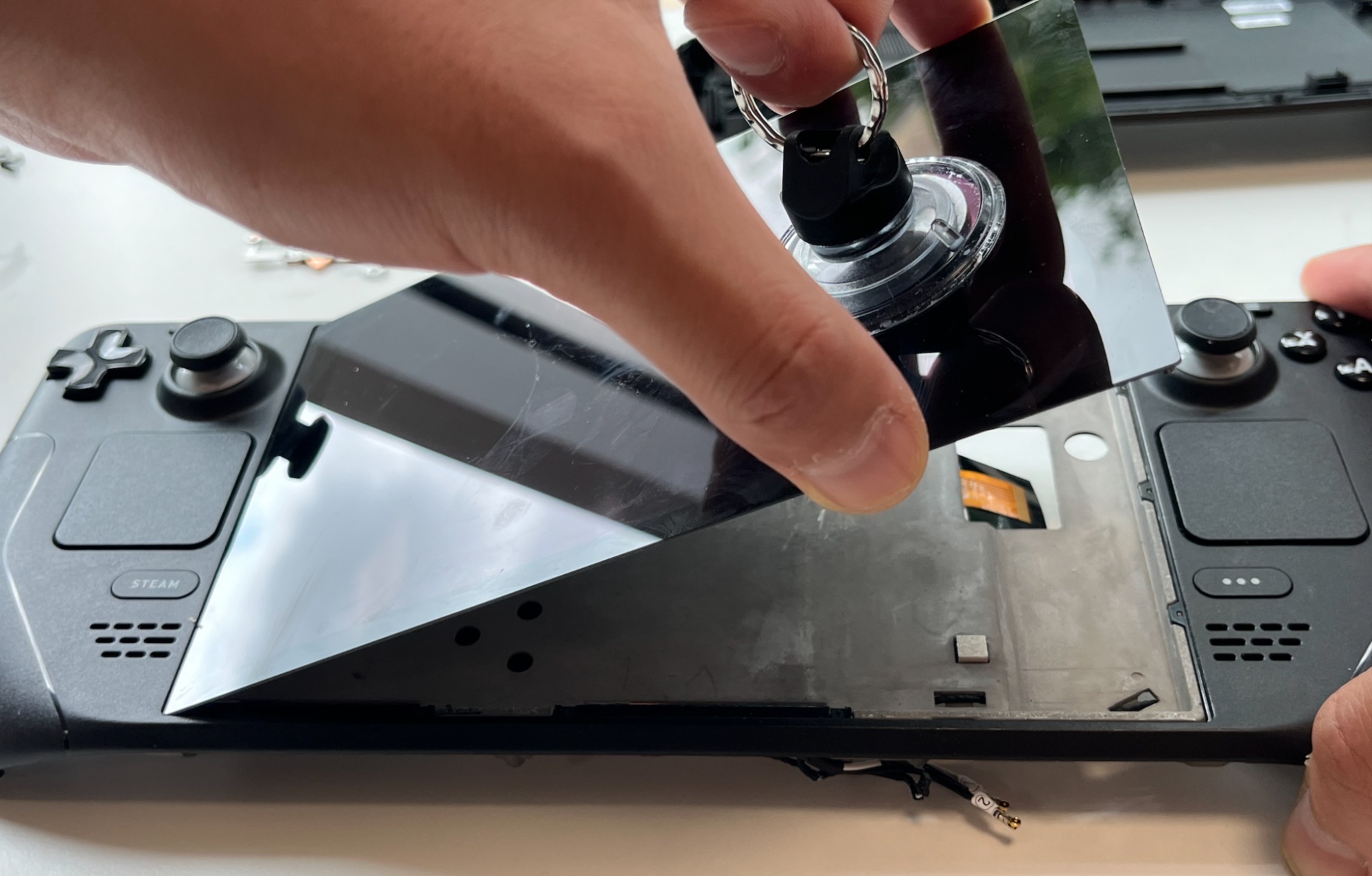
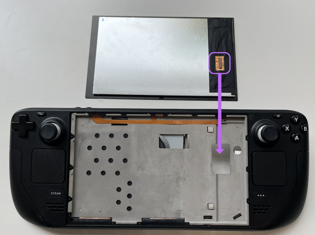
During reassembly, examine the new display adhesive and match each strip to its respective side of the display.

  • The first strip (thick) is for the left hand side edge
  • The second strip (long) is for the bottom edge
  • The third strip is for the right hand side edge
  • The fourth and fifth strips are for the top edge. Remember not to cover up the light sensor in the middle

Step 33. Align and place the adhesive strips

  1. Before peeling any of the blue liners, identify the surface to which the sticky side should adhere.
  2. Hold the exposed strip and carefully align the adhesive’s edge to the display frame’s outer edge
  3. Lay the adhesive strip onto the surface and firmly press and slide your fingers along the edge to secure it in place.
  4. Repeat the previous two steps for the remaining three display adhesive strips.

Step 34. Peel off the last adhesive liners

  1. Peel off all the plastic liners using a pair of tweezers.
  2. Be careful not to touch any exposed adhesives during this process.

Step 35. Install the new display

  1. Before you stick the new DeckHD screen, make sure to align the display connector on the back of the screen to the cut out on the Steam Deck
  2. Set the new display in place
  3. Use a microfiber cloth and slide firmly along the edges of the display to ensure a firm adhesive bond

Conclusion

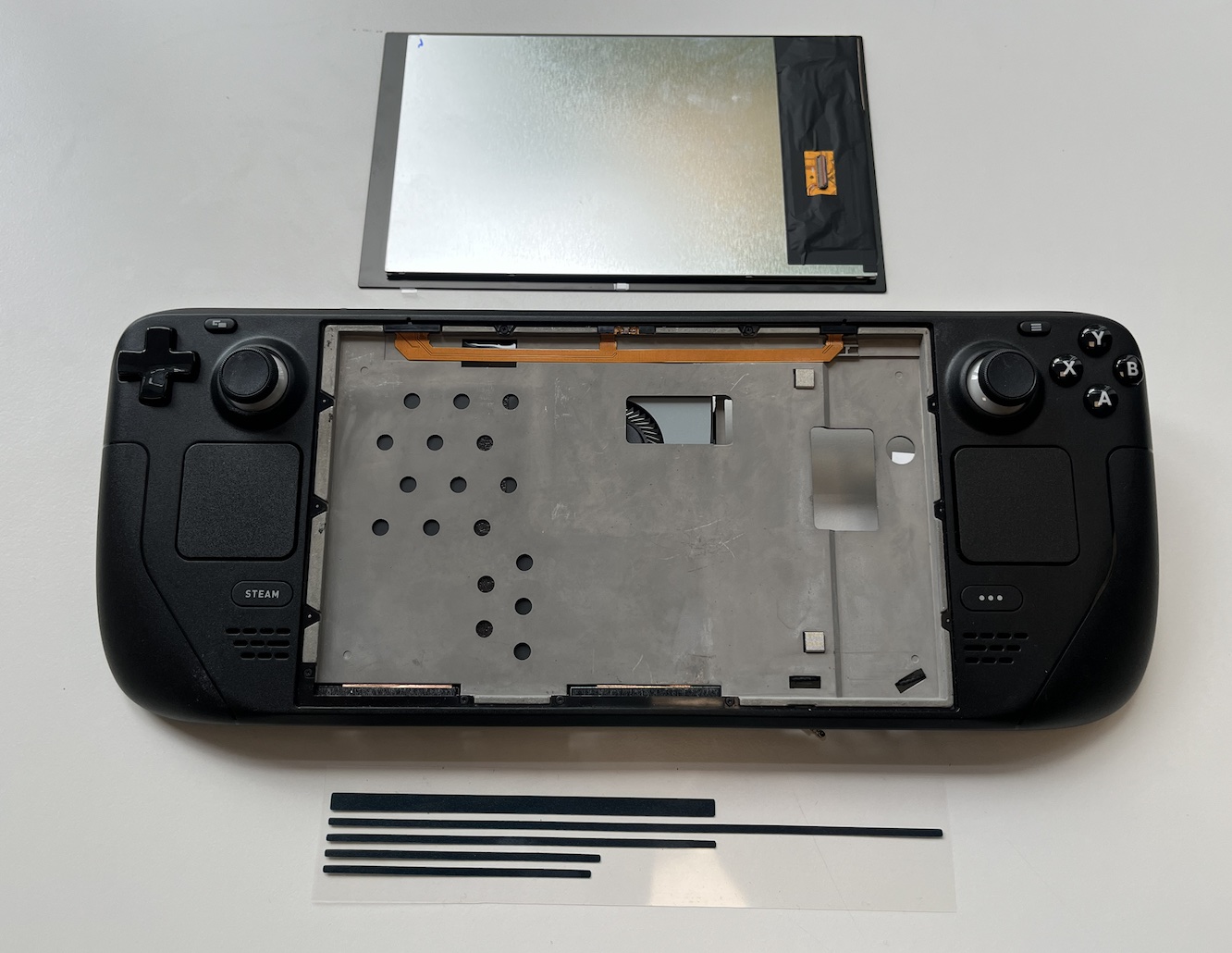
To reassemble your device, simply follow these instructions in reverse order. If you have any e-waste, remember to take it to an R2 or e-Stewards certified recycler. In case the repair didn't go as planned, you can try some basic troubleshooting or seek assistance from our Discord DeckHD community.

DeckHD is a product of FX Technology Limited.

© 2023 All rights reserved.